LASER PROJECTION LAYOUT
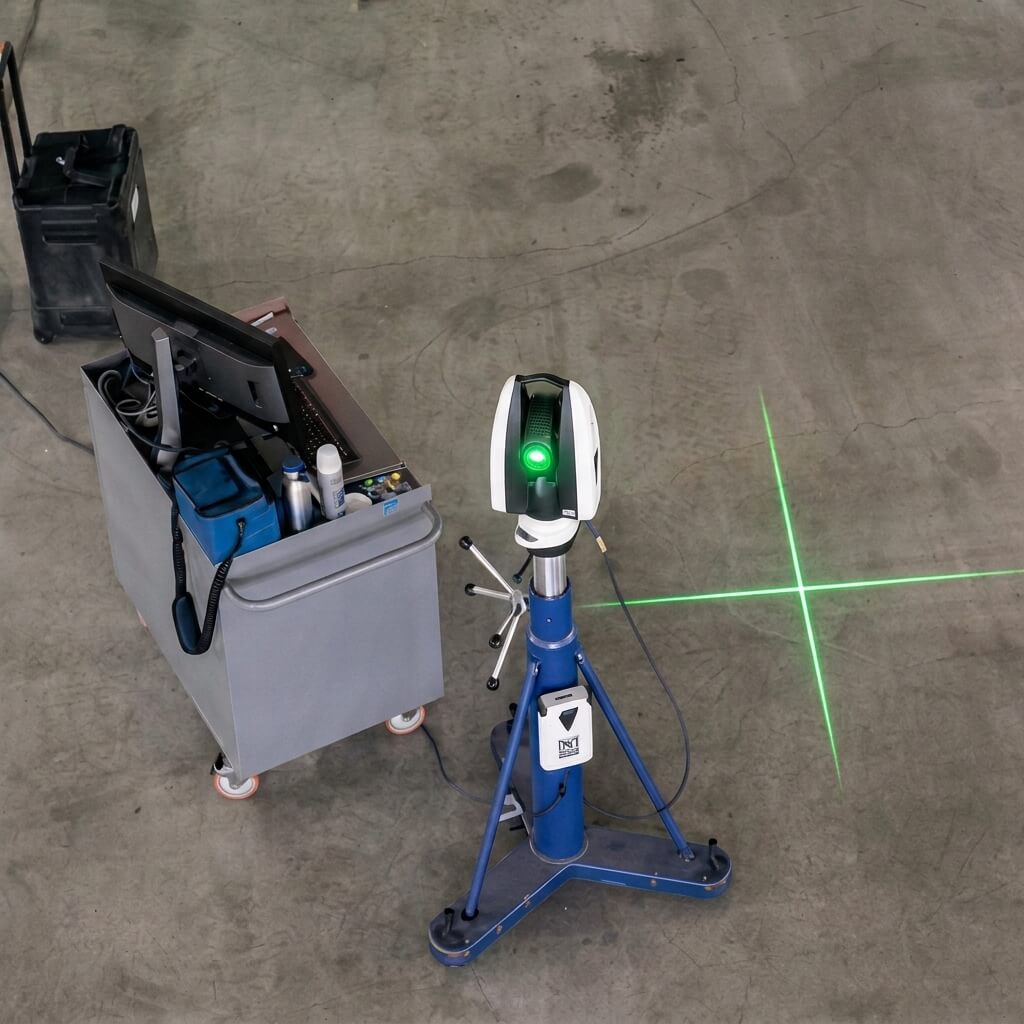
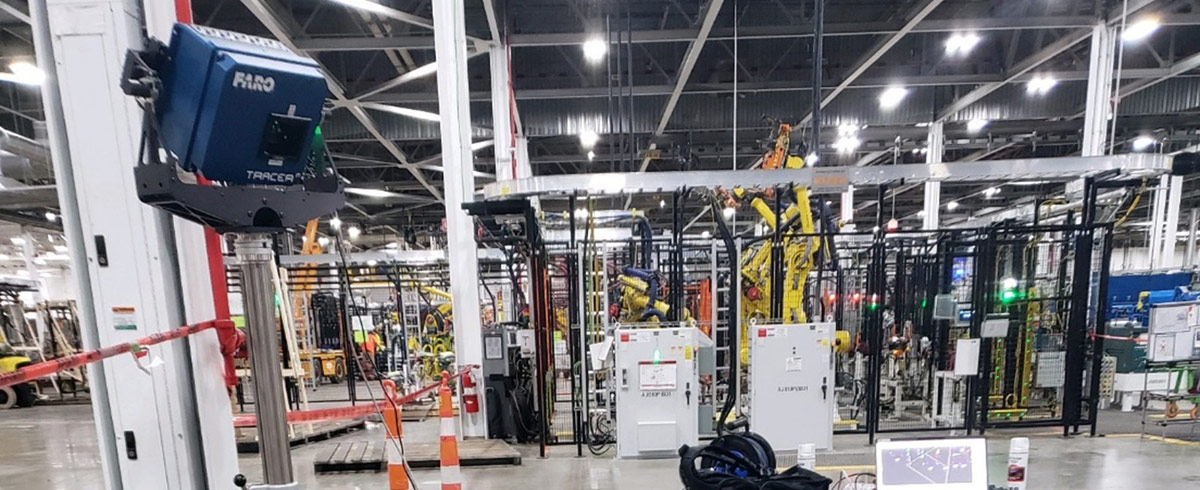
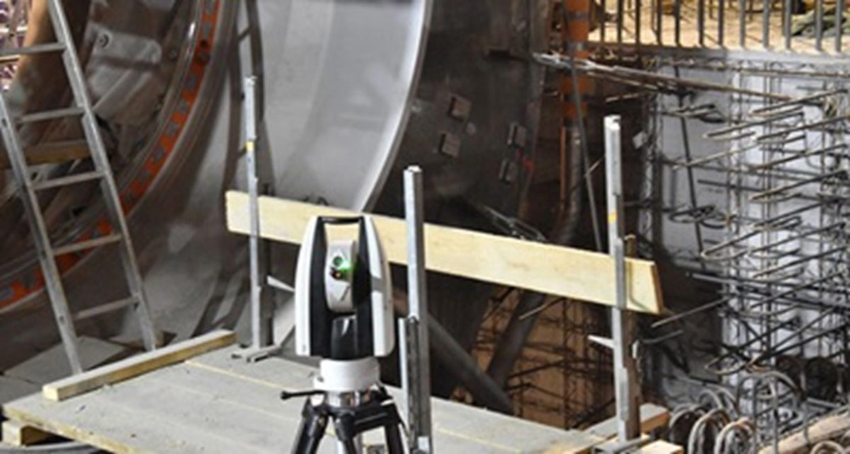
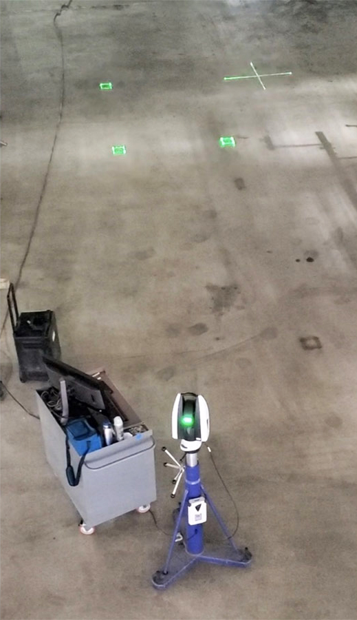
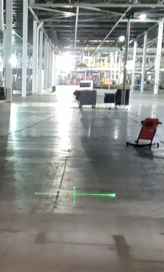
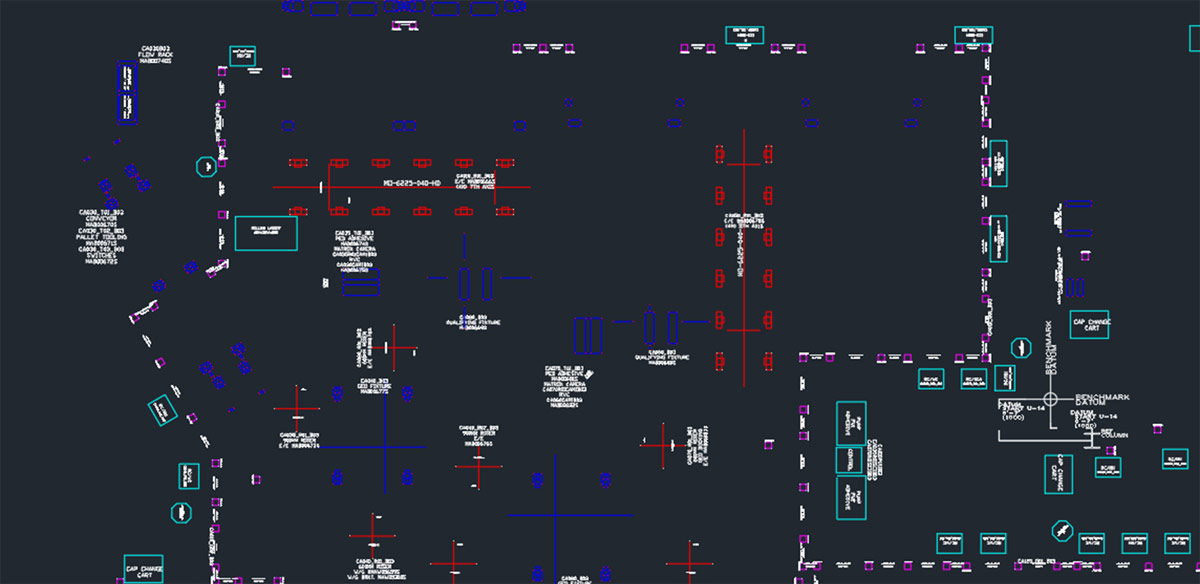
Laser trackers and Laser Projectors are used for performing real-time marking of new plant equipment. If you are retrofitting, replacing, or upgrading an existing facility, there is an even larger requirement for information, such as current machinery, robots, tools, fixtures, gantries, power supplies, pipework, walkways, barriers, cranes, fences, tanks, silos, etc. Mapping these constraints in 2D (floor plan) or 3D allows for the design, and to modify and plan the installation of any new equipment.
CAD BASED INSPECTION
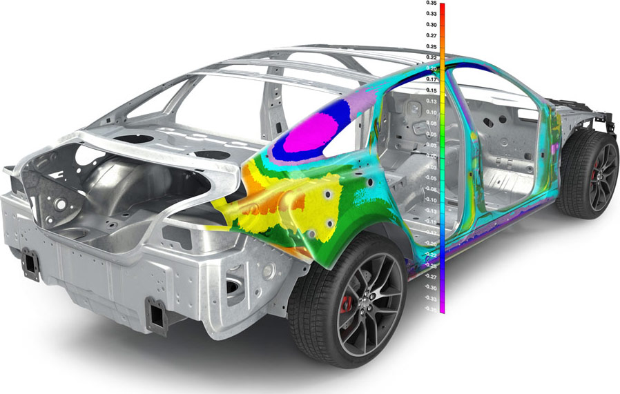
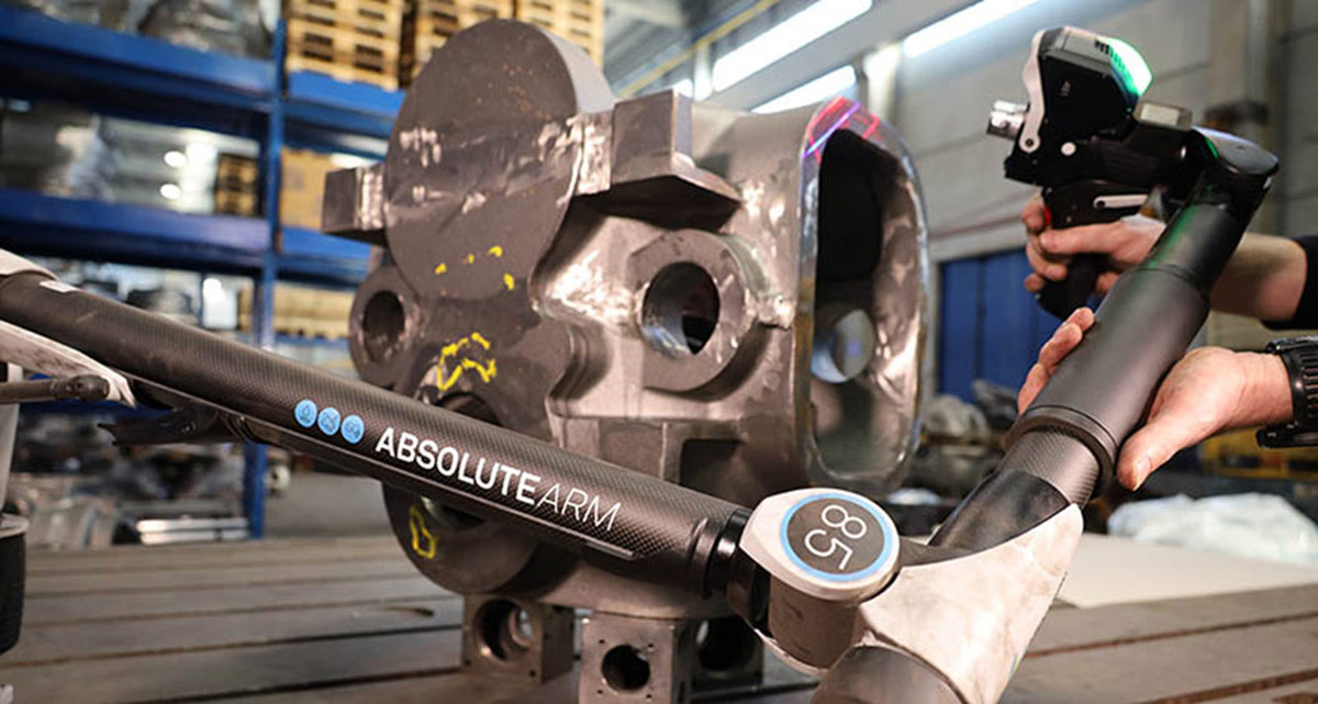
Portable measurement devices simplify the implementation of geometric dimensioning and tolerancing (GD&T) and provide efficient, easy-to-use solutions for CAD-based 3D inspections and nominal comparisons. With the help of measurement arms and laser trackers, we can utilize CAD overlays to check complex geometry against design or CAD comparison to evaluate deviations in surface form and ensure every part is machined to an exacting tolerance.
USMN (UNIFIED SPATIAL METROLOGY NETWORKS)
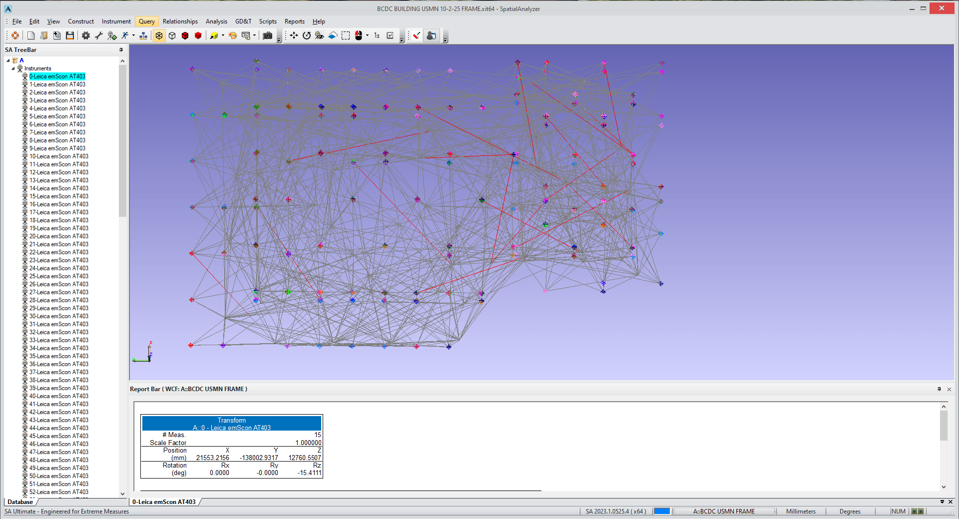
Unified Spatial Metrology Network provides answers to measurement uncertainty issues in an easy to use and understand environment. Large-scale measurement processes require more than a single measurement instrument. Examples include commercial airplane production and shipbuilding. These applications necessitate either a combination of various measurement devices or the relocation of a single instrument throughout the measurement volume in order to acquire the necessary data.
Unified Spatial Metrology Network (USMN) brings together all in-use metrology instruments and combines their instrument uncertainties in a bundle adjustment for highly precise position determinations.
In doing so, the integrated optimization algorithms calculate a posterior uncertainties of individual instrument types used as well as for adjusted point coordinates in the instrument networks.
FLOOR SURVEY
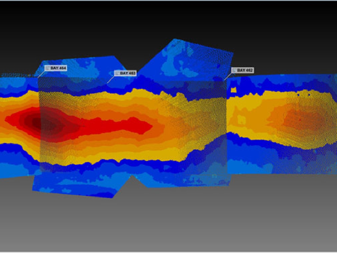
Based on the established Wave-Form Digitizer technology behind some high-end surveying tools, our equipment is powered by the first ever Scanning Absolute Distance Meter, a metrology-grade iteration of this technical principle that can locate a point to within 300 microns from up to 60 meters away. This allows us to take survey points at exact interval with very high precision. Then we can develop a color map showing any increment of elevation change.
REVERSE ENGINEERING
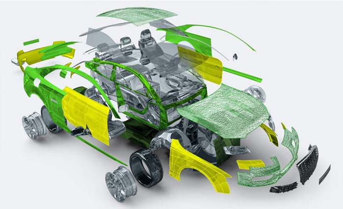
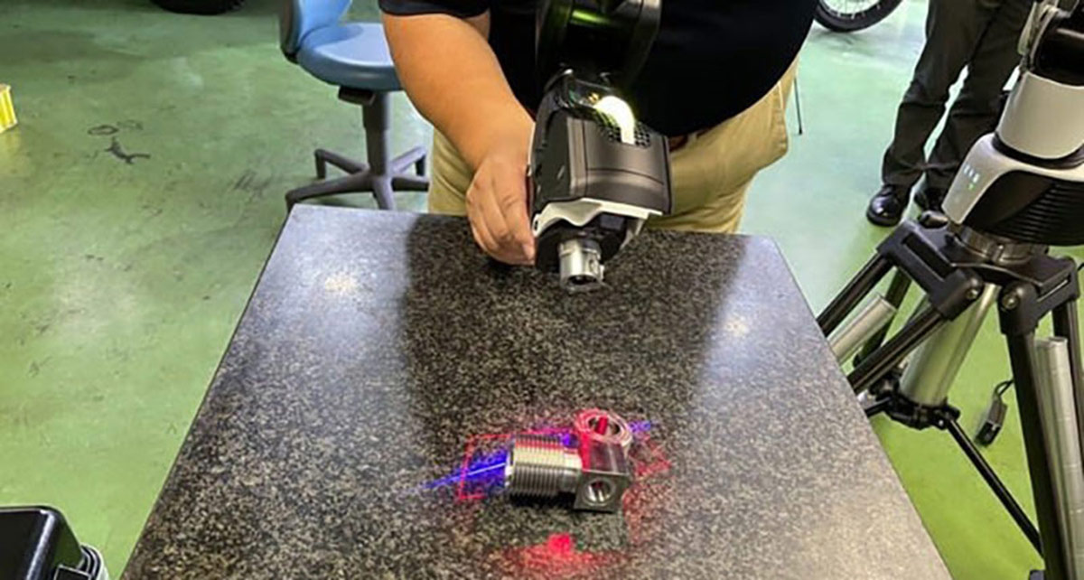
Reverse engineering is becoming a more popular method of creating a 3D model of a part without existing CAD files. Reverse engineering reconstructs classic designs and implements new ones. It can generate lost or absent design documentation and update or create as-built documentation. Create CAD data from an existing part or prototype. Compare measured data to your existing CAD model to ensure dimensional integrity.
Using non-contact 3D laser scanning and 3D documentation solutions integrate 3D modeling processes into a single step. They can provide virtual simulations of automotive interiors, support rapid prototyping in plastics manufacturing and inspect composite surfaces in aerospace assembly.
ALIGNMENTS
R&E Automated Systems provides two specialized alignment services: laser tracker alignment for machines, lines, and fixtures, and shaft alignment for rotating equipment. Each addresses a different kind of misalignment, and both protect your uptime and performance.
Laser Tracker Alignment
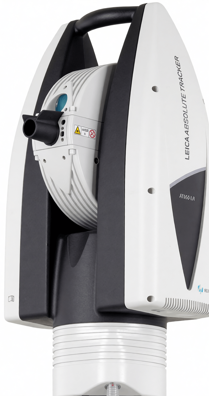
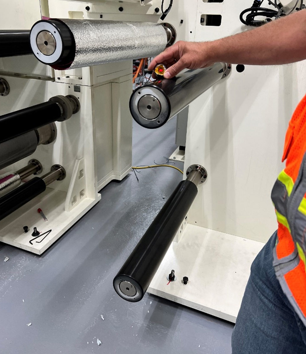
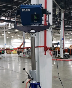
Laser trackers measure with high accuracy in three dimensions across large work areas, making them ideal for a wide range of alignment tasks, including machine tool alignment, roller and press alignment, conveyance alignment, jig and fixture alignment, and CMM alignment.
When these systems drift out of alignment, the effects show up across your operation: machine downtime, significantly reduced machine performance, increased vibration, bearing and coupling failures, and even higher power consumption. Laser tracker alignment brings your equipment back to its intended geometry so it performs the way it was designed to.
Shaft Alignment
Shaft alignment is the process of aligning two or more shafts with each other to within a tolerated margin. When alignment isn’t achieved within the required specifications, the result is shaft misalignment, either offset or angular, which leads to premature wear and damage to your systems.
We perform alignments on horizontal, vertical, and flange-mounted machines, as well as machine trains and cardan machines. This includes fans, compressors, gearboxes, support bearings, gas turbines, electric motors, engines, and pumps. Using laser shaft alignment equipment, we measure vertical and horizontal alignment, check for soft foot, and correct your machines to specification.
BIM (Building Information Modeling)
TERRESTRIAL LASER SCANNING
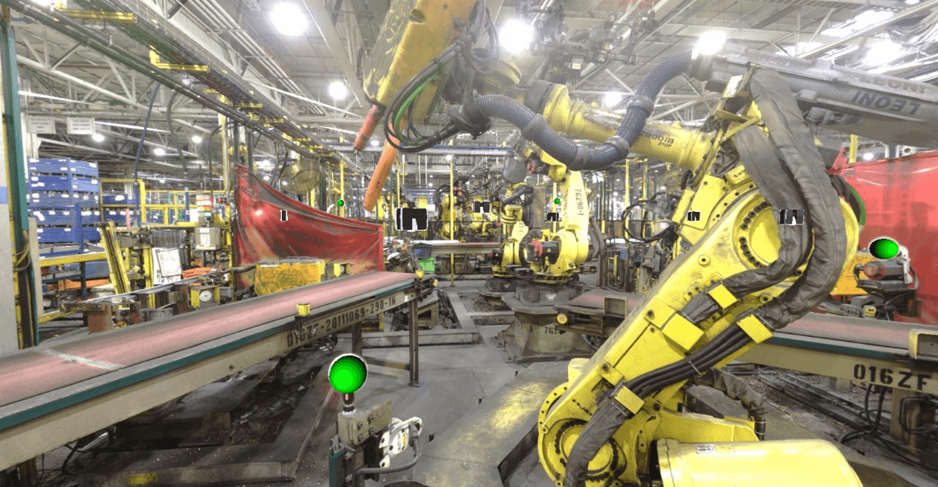
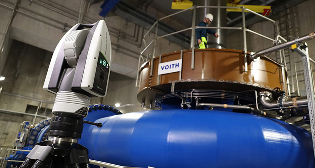
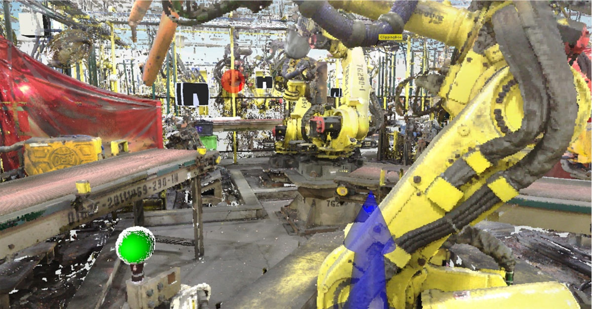
BIM (3D LASER SCANNING) is more than just a 3D model. BIM is a process of creating and managing building data throughout the building’s entire life cycle. BIM encompasses not only the geometry and spatial relationships (i.e. the 3D model), but also features about the building such as the specific information about the type of materials used, the quantity used, and how those characteristics impact the building as a whole. BIM can be thought of as a database of information ranging from project cost management to the “as-built” 3D model after construction on through the operation of the facility which can be used to actively manage the process every step of the way.
DIMENSIONAL MEASUREMENT SERVICES OVERVIEW


25 YEARS OF PROVEN PARTNERSHIP






WHAT OUR CLIENTS ARE SAYING

“When a logic conflict in our main sorting line caused an unscheduled three-hour shutdown, we couldn’t wait for a general contractor to ‘study’ the problem. We called R&E, and they had a W-2 Controls Engineer on-site who diagnosed the PLC bottleneck and had us back in production within ninety minutes. Having a partner who understands the high-stakes cost of a down-minute is invaluable.”
Marcus V.
Senior Maintenance Manager, Tier 1 Automotive Supplier
“The biggest risk in field services is the ‘contractor carousel.’ With R&E, that risk is gone. Knowing that their CWIs and Manufacturing Engineers are full-time R&E employees means we get a consistent level of professionalism and safety compliance every time. They understand our documentation standards and our culture of excellence, which simplifies my vendor management immensely.”
David K.
Purchasing Manager, North American Distribution & Logistics
“During our recent EV platform launch, our internal engineering team was stretched thin. R&E Automated provided four Robot Programmers who integrated so seamlessly into our workflow that it felt like they’d been with us for years. They didn’t just write code; they optimized our cycle times and de-risked our most aggressive production milestones. They are our first call for technical bandwidth.”
Sarah L.
Operations Director, Global OEM Assembly Plant
OTHER MANUFACTURING SERVICES

START WORKING WITH R&E
Tell us a bit about your business, your challenges, and your goals, and our experienced team will reach out to see how we can help.